
[Please excuse my English]
I really like the popular set-up of 2 servos arduino insects on youtube. When I looked at it, I always remember what BEAM robotic guys did long before that set-up became favorite. These people who are analog robot fanatics did better on the gait due to better angle between the two motors (microcore /bicore walker, etc).
However, in my opinion, none of those mentioned before look more alive than VBug1.5 (also known as Walkman) created by the founder of beam robotic, Mark Tilden. It’s using 5 motors, therefore it has more maneuverability.
Making a simple BEAM robot is not difficult, but building something as complicated as VBug1.5 could be distressing for an electronic novice like me. So, when I decided to make something like Tilden’s bugs, I had to settled with arduino platform, the easiest choice for non-engineers (or in my case, embarrassingly, an engineer wannabe).
As a result, I made Walter, a 4 legged arduino robot with 5 servos. You may wonder, if I wanted to make a look-alive bug robot then why I didn’t go with 8 or 12 servos instead. Well, I was thinking something simplest I can do to get most maneuverability I can have. I’m talking about using a lot of glue instead of making frames.
BEHAVIORS
Like many other arduino robots, Walter can avoid obstacles using HC-SR04 ultrasonic sensors. To add character as a bug, Walter also a photovore, means he is attracted to light. Photodiodes are used to detect light. There are random values generated in the arduino sketch to make Walter decides when he wants to stop to rest, and also to randomly changes his gait speed (3 speeds).When I started, I intended to have tact buttons under each of Walter’s feet so he would have a surface sensors. But the battery (a portable power bank for smartphone) costs the servos to much weight. I know tact buttons weigh almost nothing to worry to add weight, but ironically the weight of the robot is not enough to able to pressed the upside-downed buttons.
I planned to make Walter version 2 with bigger servos and then included these buttons as surface sensors.
BILL OF MATERIALS
- Controller: Arduino Pro Mini (5v, 16MHz)
- Sensors:
- 3x HC-SR04 Ultrasonic Sensors
- 4x Photodiodes (5mm)
- 4x 100kΩ resistors
- Actuators: 5x MG90S Metal Geared Micro Servos
- Power: 5200 mAH portable power bank for smartphone (2 channel output, 1 A and 2.1 A)
- Some wires and female header connectors
- 2x USB A connectors
- Toggle switch
- Coat hanger or any thin metal rod you can bend to make legs
- A lot of glue (hot glue gun, super glue, and plastic steel / epoxy glue)
 |
 |
 |
 |
 |
 |
 |
 |
 |
 |
CIRCUIT
Although they work fine for me, I think I need more experimenting with smaller values for the resistors.
ARDUINO CODES
I wrote this codes myself. That's a guarantee that this codes are a total noob work. Feel free to improve it as you see fit.WARNING: Some values need to calibrate before uploading the codes.
Read the top comments first to find which values they are. Calibration needed to find center values of each servos.

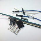
ASSEMBLY
Glues are essential for this project. I used 3 kind of glues; hot glue gun, super glue, and plastic steel / epoxy glue.At first I used white polymorph plastic, but then I switched using a lot of plastic steel epoxy. They're easier to use.

Many of these photos taken before I switched to plastic steel. Notice the amount of glues used. I meant it when I wrote glues are essential before.

The shaft is made from servo horn and spacer glued together.

I found a convenient way to put header connectors on arduino pro mini without soldering them to proto board or any pcb. Yeah.. Glues baby! (Do I start to sound like a weird glue fetish guy?)

I also used spacer as a stand to hold the arduino pro mini and ultrasonic sensors.


2 USB connectors glued together with toggle switch. The USB's would then connect to 2 channels of power bank. Although the power bank has power button itself, the button can only turn the power bank on and start open the current, but it can't cut its current itself. Hence I added a toggle switch.

Here You see the legs had redone with plastic steel epoxy.

Here is an easy set up of my photodiode and resistor. No pcb, only wires and female headers needed. Sorry I missed taking picture details of the photodiodes glued to power bank.

First time fully assembled.


Well, that's all folks, I hope you'll join the fun building this creature.
How to calibrate the servo motors? I am using 360 degree continuous rotating servo motor.
ReplyDeleteWhy are you using continuous servos? You shouldn't use continuous servos. Please read the comments in the arduino sketch. There you'll find instructions to find which codes their values need to be changed.
DeleteThanks for your reply.
DeleteHii I intend to make this project for my students as academic project. But i have some queries. From what material you made shaft(servo horn and spacer: couldnt understand these, are they readily available or made from scratch).
ReplyDeletespacers (or some call them standoffs) are something like these:
Deletehttps://www.amazon.com/s/ref=nb_sb_noss_2?url=search-alias%3Dindustrial&field-keywords=nylon+standoff&rh=n%3A16310091%2Ck%3Anylon+standoff
servo horns usually come with the servos, no need to buy them separately:
https://www.servocity.com/servos/servo-accessories/servo-attachments/servo-horns
They are things I had already lying around in my parts box. I just glued them together to made a shaft.
Do spacers need to be in specific diameter?
DeleteAnother issue is with portable power bank. What happens when power bank goes empty, i mean how to recharge them..?
ReplyDeleteCharge them using usb cable from any usb port (computers, etc) or any charger that has usb port output.
Deletewhere are the connectors connected to Aurdino pro mini board pins. I see two sets of connecting wires and also connecting bread combs soldered, can you elaborate on this detail. Plz drop your mail for clarification.
ReplyDeleteThanks and regards.
I already insert circuit diagram in my post.
DeleteAnd no, I'm sorry, I will not write my email address here.
HOw much does it cost?
ReplyDeleteI guess it will depend where you live. In my country it costs no more than $50.
Deletecan you please make a more detailed step on how to make it
ReplyDeleteCodes are already provided. Circuit diagram is also provided. Parts are all in the list. As for construction, you need to be creative. It's not a kit that has an assembly instruction. So I think it's all already there. Why don't you tell me which part you find it hasn't clear?
DeleteHere is an inspiration for the body construction if you need it: https://www.youtube.com/watch?v=sqDfYtm3opI (Mr. Michael Barratt made a better version of my Walter)
Thanks, this is great description, well done!
ReplyDeleteThank you for your kind words.
Deletehow to code it
ReplyDeleteWhat do you mean? I already provided the codes. Just copy it to your arduino IDE then upload it to your arduino board.
DeleteIf you're not familiar with arduino environment please first visit arduino.cc. There are a lot of tutorials and documentations in the site to begin.
Hello and thank you very much for sharing your knowledge and experience ! Great job !
ReplyDeleteIm a really noob in electronics so I have some few (stupid) questions.
First is where do the 5v (red) wires from servos, sonars and diodes go ?
And second is why did you stick 2 other rows of header connectors and can I get a more detailed diagram/schema about it please ?
Yeah im a real newbie from all points of view but I really love arduino based electronics and these little home made robots.
Cheers mate !
Scmb.
Hi Nerko.
DeleteI see you haven't used to see circuit schematics. That's alright, and these aren't stupid questions.
1. All 5v lines connected to 5v power source which in this case is the portable power bank. Notice there's also 5v coming out from one of the USB connectors? That's the power source. That particular USB connector goes to 2.1A channel of the power bank. I didn't write it in the schematics, but the other USB also provide 5v power (like any others usb power), and you can see it connected to arduino's 5v pin, as the arduino also need to be 5v powered.
Then why did I separate power sources between arduino and other electronics? Because the servos drawn a lot of current, and if the arduino shared power with the servos, the arduino would sometimes restart itself due to lost power 'stealed' by the servos.
2. Actually your second question is still related to the matter of power line. Those two rows added on the each side of the arduino are power lines. Middle rows are positive (5v) come from 2.1A USB, and outside rows are negative (ground). With those rows I can conveniently connect my servos' headers and other electronics' headers to arduino's pins and power line. So just solder the middle rows together (left and right side also connected using a wire) to 2.1A USB. Do the same with the negative/ground line (outside rows) to ground. Remember to connect all the ground.
Alright Nerko, time to grab your solder iron.
Cheers!
Oooh dam' I couldn't expect better and more clear answer than this. Thanks a lot and may God bless you !
DeleteYour project is very impressive. But I want to ask to you. Is the power bank for the flow of electricity can be replaced with ordinary batteries? How many batteries should Volt have to be connected to the robot?
ReplyDeleteYes, of course it can. Power bank is actually a regulated batteries anyway.
DeleteWell, you can see in the schematic attached in the post that the arduinos need 5v, and so do the ultrasonic sensors.
With the resistor value I use in the schematic I think the photodiodes can still take higher voltage (I already mentioned in the post that I might have put the resistors value too high).
The servos can take up to 6v. But I chose not to push the voltage to their limit.
Arduino pro mini already have voltage regulator on board that can take up to 9v through raw pin (be careful not to connect more than 5v to 5v pin). Say you're going to power the arduino with 7.4 lithium, maybe arduino's 5v pin can still provide enough current for the three ultrasonic sensors, but not for the servos. So you'll still need a voltage regulator anyway for powering the servos separately.
So for the conclusion, the easiest way is to step-down your batteries using voltage regulator to 5v, and use it to power all the electronics. Make sure your batteries and regulator can provide a large current, cause those servos are beasts!
Okay. For the servo, you say there are 5 servings, 2 pieces for the front, 2 more for the back, and 1 piece for the middle. The middle part where it is placed servo?
DeleteThis comment has been removed by the author.
DeleteAnd one more, can you show how to assemble the robot? It will be very helpful in the work of the robot. Can you share my tutorial video?
DeleteCan this robot be controlled using Bluetooth friend???
ReplyDeleteNope.
DeleteI have a problem while uploading the script. can you help me?
ReplyDeleteI don't know. Maybe, depends on the problem.
Deletei have a question ? what is the fifth servo doing in this project ? which is in the middle?
ReplyDeleteThe fifth servo is making vertical movement for the legs. It's between the two front servos.
Deleteokay thankyou, and please tell me about the two different grounds one you have given to switch and second to arduino from where to connect them
ReplyDeleteWhat 'two different grounds'? All grounds must be connected together.
Deleteyeah i have done that but there's a problem in my robot its going in backward direction rather than front, i have checked everything its all same as yours but havent got a solution, can you help me at this ?
Deleteand also tell me the serial number of photodiodes you have used
Deletehey, i'm fairly new to electronics and i don't really understand the concept of grounding (the 3 lines on the circuit diagram) , does that mean i just leave it hanging or do i insulate it or what
ReplyDeletesorry for the basic question, using this project as my introduction to electronics
No need to sorry. Connect all those grounds to the batteries' negative pole.
Delete(The fifth servo is making vertical movement for the legs)
ReplyDeleteWhy we need to do this? Is it make robot turn left or right?
Hello. It's such a great project. I wanna ask, can i just use the 9V battery instead of using a power bank? Thankyou :)
ReplyDeleteFirst; I don't think standard 9V batteries have enough amps for the servos. Second; if you find a 9V battery that can supply high amps, you're still going to need a 5V voltage regulator.
DeleteThis comment has been removed by the author.
ReplyDeleteHello dear friend, I comme back to tell you that I made it. Thanks to you and your great work I made the same quadruped insect robot... Not completely the same, check out a litlle video I made of it : https://streamable.com/rasrl
ReplyDeleteThat's excellent! Yours looks beautiful.
DeleteAre those 18650 batteries? Are they connected in series or parallel? What kind of voltage regulator are you using?
Good job man! I wish you shared your video in youtube.
Yeah 2 18650 batteries on 2 separate circuits to power up 3 of 5 servos and the other one to power up the others 2 servos + arduino and all detectors.
ReplyDeleteWith a MT3608 step up converter delivering each 5V and 2A (widely enough, doesn't even heat up).
But this supply circuit is temporary because I'm waiting for 2 li-po batteries to make it look thiner.
But now Im hesitating bcause with these 2 18650 batteries it looks good too.
Nah, you are the one who did good job mate. I was only following your steps.
I will made a better video of it and will post it soon on YouTube.
Will sharz the link
Hello , Can you tell me how exactly to upload code to the pro mini cuz i got errors.
ReplyDeleteWithout any further details on how you uploaded the code and what the errors are, I can only assume generic misstep people usually did: Have you change the board selection on arduino IDE to arduino pro mini and select processor setting to whatever atmega chip on your pro mini board?
DeleteThis comment has been removed by the author.
ReplyDeleteno worries ,was sort of bad connection
ReplyDeleteI have question on the switch part. On the diagram there are 3 wires that came out ( 5v from 1st usb, 5v from the 2nd usb , 1 ground from the switch ), but then u connect 4 wires with the 5v and ground on the arduino. From where it that 4th wire?
ReplyDeleteHello again, dear friend. Everything on this project works fine except the part where it should chase light. I switched the resistors to 82k ohm, switched the places of photodiods legs but still cant make it chase light. For light source im using my phones lighter. Do i need to use more powerful light source and can u give some info bout this part?
ReplyDeleteHi. Have you checked the photodiodes polarity? They should connected in reverse biased manner. The cathodes should connect to 5v and the anodes should connect to resistors/analog arduino pins. I think I messed up on the complete circuit scheme. Please refer to detailed photodiode connection image.
Deletehttps://imgur.com/VWc2IzU here is the image all 4 diodes are connected like this.
DeleteHi,
Deletei have a different problem. Everything works except the front sonar. I replaced the sonar with a new one...not working...then i checked the cables all work...so finally i decided to use a different arduino board...still not working no matter what i do, any idea ?
Can we use 3 servo motors instead of 5 ?
ReplyDeleteHello. I really appreciate your work and I was inspired to make one. I have a question. Is it ok to use SG90s rather than MG90s Servo motor ? I will substitute the SG90s because my budget is so tight :) Thank you in advance :)
ReplyDeleteGreat Info about AI. Thanks For Providing
ReplyDeleteArtificial Intelligence and Robotics
Tech News In India
Technology in India Today
Artificial Intelligence Pros and Cons
Artificial Intelligence use Cases
hello sir, I appreciate the hard word put in this project and sharing the same with us. I have only one question which i did not understand...what is the fifth servo for? and how is it mechanically connected.....i cant make out from the photos you have shown. Please only if you could give me the detailed fitting for the fifth servo, ill be grateful...Thank you once again
ReplyDeletehow i will upload the code?
ReplyDeleteWhich libraries should we download to use this code
ReplyDeleteTed apa kabarlu? Msh inget gua ga?
ReplyDeleteHi where should I fix the 5th horizontal servo plsss tell
ReplyDeleteAnyone help please
ReplyDeleteHi. I have a question. In what conditions did walter will run and walk?
ReplyDeletehello sir, I appreciate the hard word put in this project and sharing the same with us. I have only one question which i did not understand...what is the fifth servo for? and how is it mechanically connected.....i cant make out from the photos you have shown. Please only if you could give me the detailed fitting for the fifth servo, ill be grateful...
ReplyDeleteCan i ask whether we can use a arduino uno instead of arduino pro mini
ReplyDeletewhen i upload the codes it says that "servo.h: no such file or directory
ReplyDeleteMy servos are not working with power output so for that I had used pca9856 servo driver
ReplyDeleteSo can you please help me tell about what amendments I would made in code to connect aurdino with driver?